Let's get PWM Using Spartan 3E
Dans la meme s�rie de tutoriels que j'ai fait au but de la d�couverte de technologie FPGA et en particulier la carte Spartan 3E, Aujourd'hui je vais vous montrer comment on fait pour generer un signal PWM (pulse widh modulation), vous expliquer les �tapes de programmation que j'ai fait en passant par un test pratique d�monstratif.

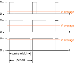
La modulation de largeur d'impulsions (MLI ; en anglais : Pulse Width Modulation, soit PWM), est une technique couramment utilis�e pour synth�tiser des signaux continus � l'aide de circuits � fonctionnement tout ou rien, ou plus g�n�ralement � �tats discrets.
Le principe g�n�ral est qu'en appliquant une succession d'�tats discrets pendant des dur�es bien choisies, on peut obtenir en moyenne sur une certaine dur�e n'importe quelle valeur interm�diaire.
Ce ph�nom�ne est fortement recommand� pour assurer la variation de vitesse de moteur a courant continu, aujourd'hui je vais vous d�montrer comment on peut g�n�rer un signal PWM d'une carte FPGA Spartan 3E et visualiser son pr�sence sur des diodes LEDs.

Passons maintenant au programmation;
Voici le programme du projet :
PWM Top Code :
----------------------------------------------------------------------------------
-- Company: There is no company
-- Engineer: Aymen Lachkhem
--
-- Create Date:    02:27:11 03/27/2016
-- Design Name:
-- Module Name:    counter - Behavioral
-- Project Name:
-- Target Devices:
-- Tool versions:
-- Description:
--
-- Dependencies:
--
-- Revision:
-- Revision 0.01 - File Created
-- Additional Comments:
--
----------------------------------------------------------------------------------

library IEEE;
use IEEE.STD_LOGIC_1164.ALL;
use IEEE.STD_LOGIC_ARITH.ALL;
use IEEE.STD_LOGIC_UNSIGNED.ALL;
entity top is
    Port (
    clk : in std_logic;
  pwm_out : out std_logic;
    rotary_a : in std_logic;
    rotary_b : in std_logic
);end top;

architecture Behavioral of top is
component pwm
 port(
  clk: in std_logic;
  pwm_var: in std_logic_vector(7 downto 0);
  pwm_out: out std_logic);
 end component;
 component rotary
 port(
  pwm_var : out std_logic_vector(7 downto 0);
      rotary_a : in std_logic;
      rotary_b : in std_logic;
      clk : in std_logic);
 end component;
signal pwm_var: std_logic_vector (7 downto 0);
begin
U1 : pwm
 port map(
  clk => clk,
  pwm_var=>pwm_var,
  pwm_out=>pwm_out
 );
U2 : rotary
 port map(
 pwm_var=>pwm_var,
   rotary_a=>rotary_a,
   rotary_b=>rotary_b,
   clk =>clk
 );
end Behavioral;
Pour les configurations physiques de mon programme avec la carte Spartan 3E j'ai choisis ces entr�es sorties:
NET "clk" PERIOD = 20.0ns HIGH 50%;
NET "clk" LOC = "C9" | IOSTANDARD = LVTTL;
NET "rotary_a" LOC = "K18" | IOSTANDARD = LVTTL | PULLUP;
NET "rotary_b" LOC = "G18" | IOSTANDARD = LVTTL | PULLUP;
NET "pwm_out" LOC = "D5" | IOSTANDARD = LVTTL | SLEW = SLOW | DRIVE = 6 ;
Le programme TOP il inclus deux component que j'ai �cris en VHDL aussi :
PWM  Code :
----------------------------------------------------------------------------------
-- Company: There is no company
-- Engineer: Aymen Lachkhem
--
-- Create Date:    02:27:00 03/27/2016
-- Design Name:
-- Module Name:    counter - Behavioral
-- Project Name:
-- Target Devices:
-- Tool versions:
-- Description:
--
-- Dependencies:
--
-- Revision:
-- Revision 0.01 - File Created
-- Additional Comments:
--
----------------------------------------------------------------------------------

library IEEE;
use IEEE.STD_LOGIC_1164.ALL;
use ieee.numeric_std.all;

entity pwm is
port(
 clk: in std_logic;
 pwm_var: in std_logic_vector(7 downto 0);
 pwm_out: out std_logic

);
end pwm;
architecture Behavioral of pwm is
signal counter: std_logic_vector(7 downto 0):="00000000";
signal max_counter: std_logic_vector(7 downto 0):="11111111";
begin
process(clk)
begin
 if rising_edge(clk) then
  counter <= std_logic_vector( unsigned(counter) + 1 );
  if counter=max_counter then
   counter<="00000000";
  else
   if counter<pwm_var then
    pwm_out<='1';
   else
    pwm_out<='0';
   end if;
  end if;
 end if;
end process;
end Behavioral;
Et
ROTARY ENCODER  Code :
----------------------------------------------------------------------------------
-- Company: There is no company
-- Engineer: Aymen Lachkhem
--
-- Create Date:    02:24:42 03/27/2016
-- Design Name:
-- Module Name:    counter - Behavioral
-- Project Name:
-- Target Devices:
-- Tool versions:
-- Description:
--
-- Dependencies:
--
-- Revision:
-- Revision 0.01 - File Created
-- Additional Comments:
--
----------------------------------------------------------------------------------

library IEEE;
use IEEE.STD_LOGIC_1164.ALL;
use IEEE.STD_LOGIC_ARITH.ALL;
use IEEE.STD_LOGIC_UNSIGNED.ALL;

entity rotary is
    Port (         pwm_var : out std_logic_vector(7 downto 0);
                  rotary_a : in std_logic;
                  rotary_b : in std_logic;
                       clk : in std_logic
);end rotary;

architecture Behavioral of rotary is
signal      rotary_a_in : std_logic;
signal      rotary_b_in : std_logic;
signal        rotary_in : std_logic_vector(1 downto 0);
signal        rotary_q1 : std_logic;
signal        rotary_q2 : std_logic;
signal  delay_rotary_q1 : std_logic;
signal     rotary_event : std_logic;
signal      rotary_left : std_logic;

signal      led_pattern : std_logic_vector(7 downto 0):= "00000000";
begin

  rotary_filter: process(clk)
  begin
    if clk'event and clk='1' then
      rotary_a_in <= rotary_a;
      rotary_b_in <= rotary_b;
      rotary_in <= rotary_b_in & rotary_a_in;

      case rotary_in is

        when "00" => rotary_q1 <= '0';
                     rotary_q2 <= rotary_q2;

        when "01" => rotary_q1 <= rotary_q1;
                     rotary_q2 <= '0';

        when "10" => rotary_q1 <= rotary_q1;
                     rotary_q2 <= '1';

        when "11" => rotary_q1 <= '1';
                     rotary_q2 <= rotary_q2;

        when others => rotary_q1 <= rotary_q1;
                       rotary_q2 <= rotary_q2;
      end case;
    end if;
  end process rotary_filter;
  direction: process(clk)
  begin
    if clk'event and clk='1' then
      delay_rotary_q1 <= rotary_q1;
      if rotary_q1='1' and delay_rotary_q1='0' then
        rotary_event <= '1';
        rotary_left <= rotary_q2;
       else
        rotary_event <= '0';
        rotary_left <= rotary_left;
      end if;

    end if;
  end process direction;
  -- PWM control.
  led_display: process(clk)
  begin
    if clk'event and clk='1' then
      if rotary_event='1' then
        if rotary_left='1' then
    led_pattern<=led_pattern+'1'; --INCREASE
         else
    led_pattern<=led_pattern-'1'; --DECREASE
        end if;
      end if;
      pwm_var <= led_pattern;
    end if;
  end process led_display;
end Behavioral;
Le reste c'est d�impl�menter le programme pour avoir ceci :
No comments:
Post a Comment