Thursday, March 31, 2016

CoolRunner II CPLD : Basic Tutorials

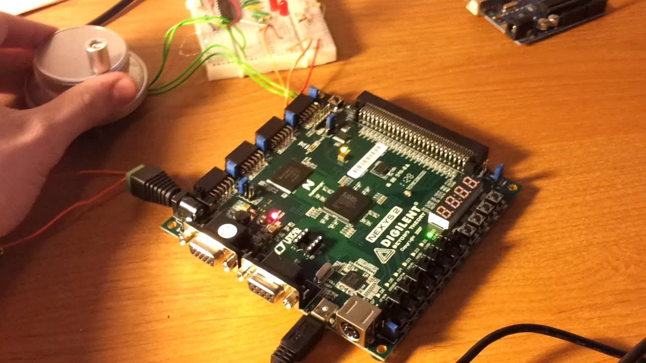
Bonjour, Aujourd'hui j'ai choisi de vous parl� un peu de la carte CoolRunner II, ses points forts, ses points faibles, ainsi la fa�on de laquelle on pourra la programmer, Ensuite je vais r�aliser un petit test sur cette carte pour v�rifier sa fonctionnement interne.

CoolRunner-II CPLD, oblique.

CoolRunner Device, elle est d�sign�e pour �tre capable a r�aliser les taches qui n�cessite une petite consommation d��nergie avec une haute performance. 
    
CoolRunner est une CPLD avant tout, lorsque on parle de CPLD on parle de :

PAL, GAL, CPLD et EPLD, de conception plus ancienne, utilisent des � macrocellules � logiques, compos�es d'un r�seau combinatoire de portes ET et OU afin d'impl�menter des �quations logiques. Des bascules sont disponibles seulement dans les blocs d'entr�e-sortie. Un composant contient de quelques dizaines � quelques centaines de macrocellules.
Comme le routage est fixe, les temps de propagations sont born�s et permettent une fr�quence de fonctionnement �lev�e et ind�pendante du design. Par contre, l'utilisation des ressources n'est pas optimale (tout terme non utilis� dans une �quation logique �quivaut � des portes perdues), avec des taux d'utilisation d'environ 25 %.
On distingue les CPLD des autres PLD car ils contiennent l'�quivalent de plusieurs composants PLD, reli�s par une matrice d'interconnexion.
Afficher l'image d'origine 
Cette derniere est une parfaite platform capable a aid�e les designers de CPLD a mieux developper leurs taches.
En anglais, le CoolRunner est d�finit g�n�ralement par high performance, low-power CPLD. du coup on peu conclure que cette derniere et vu au faible energie de consommation ainsi de traitement de donn�es dedans elle est bien capable a sauvegarder l'energie dedans.
   
Elle inclut 4 block de 12 pin Pmod portes qui nous facilites sont interfa�age au milieu externe tel que les servomoteurs, les capteurs, ... .
La carte CoolRunner 2 un mini usb port capable a l'alimenter et la programmer.
Aussi elle inclut :
  • An 8 MHz fixed-frequency oscillator and a socket for a crystal oscillator
  • DataGATE switch
  • Requires a USB A to mini-B cable for power and configuration (not included)
  • Four 12-pin Pmod ports
  • Four 7 Segment Digit
Vous pouvez absolument lire les fichiers techniques de cette derni�re pour mieux comprendre son fonctionnement.

Aujourd'hui pour debuter avec CoolRunner 2 j'ai commencer par un tout petit simple programme en faite, j'ai une entr� "a" et deux sorties "b" et "c", la cas ou "a" est au niveau haut "b" va la suivre et "c" sera au niveau bas et vis vers sa.
Les logiciels que j'aurai besoin pour r�aliser mon objectif sont:

1. ISE 

R�sultat de recherche d'images pour "ise xilinx logo"


2. Adept
R�sultat de recherche d'images pour "adept fpga logo"


Voici le programme  du projet :

----------------------------------------------------------------------------------
-- Company:
-- Engineer:
--
-- Create Date: 20:08:10 03/31/2016
-- Design Name:
-- Module Name: button_led - Behavioral
-- Project Name:
-- Target Devices:
-- Tool versions:
-- Description:
--
-- Dependencies:
--
-- Revision:
-- Revision 0.01 - File Created
-- Additional Comments:
--
----------------------------------------------------------------------------------
library IEEE;
use IEEE.STD_LOGIC_1164.ALL;

-- Uncomment the following library declaration if using
-- arithmetic functions with Signed or Unsigned values
--use IEEE.NUMERIC_STD.ALL;

-- Uncomment the following library declaration if instantiating
-- any Xilinx primitives in this code.
--library UNISIM;
--use UNISIM.VComponents.all;

entity button_led is
Port ( a : in STD_LOGIC;
b : out STD_LOGIC;
c : out STD_LOGIC);
end button_led;

architecture Behavioral of button_led is

begin
coolrunner2 : process(a)
begin
if (a='1')then
b <= '1';
c <= '0';
else
b <= '0';
c <= '1';
end if ;
end process;

end Behavioral;


Dans la vid�o si dessous j'ai vous expliqu�e pas � pas comment faut d�buter un projet CoolRunner 2 et le programmer avec Adept.

Pour les autres tests sur cette carte qui n�cessite l'utilisation de signal d'horloge (CLOCK), il faut bien mettre en compte que cette carte nous offre 3 valeurs de signal d'horloge pour les utiliser avec nos propres besoins. 
   
Comme �a se voit si dessus la valeur de signal d'horloge (clock) sera fix�e par la position de Jumper JP1 fournit sur la carte.
Les valeurs de signal d'horloge offert par Xilinx sont 10Khz, 100Khz et 1 Mhz. 
Il faut bien noter que ces fr�quences sont des hautes fr�quences pour qu'ils seront adapt�es avec les yeux d��tre humain pour ceci le meme principe qu'on a pratiquer pour fournir un clock lent avec le Spartan3E on pourra l'appliquer avec la CoolRunner 2 CPLD, il suffit de bien calculer le fr�quence voulu.

Posons ici que j'ai besoin de diviser un clock de 2 Mhz vers un clock de 1 Mhz. 

DivideByTwoCircuit.gif
Comme �a se voit ici, on a que pratiquer ce technique, il suffit de boucler la sortie du Flip-Flop invers�e vers l'entr�.
L'application de cette technique nous offrira le fr�quence qu'on cherche.


Monday, March 28, 2016

Generate PWM Signal From Spartan 3E

Let's get PWM Using Spartan 3E

Dans la meme s�rie de tutoriels que j'ai fait au but de la d�couverte de technologie FPGA et en particulier la carte Spartan 3E, Aujourd'hui je vais vous montrer comment on fait pour generer un signal PWM (pulse widh modulation), vous expliquer les �tapes de programmation que j'ai fait en passant par un test pratique d�monstratif.


Afficher l'image d'origine

La modulation de largeur d'impulsions (MLI ; en anglais : Pulse Width Modulation, soit PWM), est une technique couramment utilis�e pour synth�tiser des signaux continus � l'aide de circuits � fonctionnement tout ou rien, ou plus g�n�ralement � �tats discrets.
Le principe g�n�ral est qu'en appliquant une succession d'�tats discrets pendant des dur�es bien choisies, on peut obtenir en moyenne sur une certaine dur�e n'importe quelle valeur interm�diaire.

R�sultat de recherche d'images pour "pwm mli definition"


Ce ph�nom�ne est fortement recommand� pour assurer la variation de vitesse de moteur a courant continu, aujourd'hui je vais vous d�montrer comment on peut g�n�rer un signal PWM d'une carte FPGA Spartan 3E et visualiser son pr�sence sur des diodes LEDs.


R�sultat de recherche d'images pour "FPGA pwm"  

Passons maintenant au programmation; 


Voici le programme  du projet :


PWM Top Code :

----------------------------------------------------------------------------------
-- Company: There is no company
-- Engineer: Aymen Lachkhem
--
-- Create Date: 02:27:11 03/27/2016
-- Design Name:
-- Module Name: counter - Behavioral
-- Project Name:
-- Target Devices:
-- Tool versions:
-- Description:
--
-- Dependencies:
--
-- Revision:
-- Revision 0.01 - File Created
-- Additional Comments:
--
----------------------------------------------------------------------------------

library IEEE;
use IEEE.STD_LOGIC_1164.ALL;
use IEEE.STD_LOGIC_ARITH.ALL;
use IEEE.STD_LOGIC_UNSIGNED.ALL;
entity top is
Port (
clk : in std_logic;
pwm_out : out std_logic;
rotary_a : in std_logic;
rotary_b : in std_logic
);end top;

architecture Behavioral of top is
component pwm
port(
clk: in std_logic;
pwm_var: in std_logic_vector(7 downto 0);
pwm_out: out std_logic);
end component;
component rotary
port(
pwm_var : out std_logic_vector(7 downto 0);
rotary_a : in std_logic;
rotary_b : in std_logic;
clk : in std_logic);
end component;
signal pwm_var: std_logic_vector (7 downto 0);
begin
U1 : pwm
port map(
clk => clk,
pwm_var=>pwm_var,
pwm_out=>pwm_out
);
U2 : rotary
port map(
pwm_var=>pwm_var,
rotary_a=>rotary_a,
rotary_b=>rotary_b,
clk =>clk
);
end Behavioral;


Pour les configurations physiques de mon programme avec la carte Spartan 3E j'ai choisis ces entr�es sorties: 
NET "clk" PERIOD = 20.0ns HIGH 50%;
NET "clk" LOC = "C9" | IOSTANDARD = LVTTL;
NET "rotary_a"     LOC = "K18" | IOSTANDARD = LVTTL | PULLUP;
NET "rotary_b"     LOC = "G18" | IOSTANDARD = LVTTL | PULLUP;
NET "pwm_out" LOC = "D5" | IOSTANDARD = LVTTL | SLEW = SLOW | DRIVE = 6 ;


Le programme TOP il inclus deux component que j'ai �cris en VHDL aussi :


PWM Code :

----------------------------------------------------------------------------------
-- Company: There is no company
-- Engineer: Aymen Lachkhem
--
-- Create Date: 02:27:00 03/27/2016
-- Design Name:
-- Module Name: counter - Behavioral
-- Project Name:
-- Target Devices:
-- Tool versions:
-- Description:
--
-- Dependencies:
--
-- Revision:
-- Revision 0.01 - File Created
-- Additional Comments:
--
----------------------------------------------------------------------------------

library IEEE;
use IEEE.STD_LOGIC_1164.ALL;
use ieee.numeric_std.all;

entity pwm is
port(
clk: in std_logic;
pwm_var: in std_logic_vector(7 downto 0);
pwm_out: out std_logic

);
end pwm;
architecture Behavioral of pwm is
signal counter: std_logic_vector(7 downto 0):="00000000";
signal max_counter: std_logic_vector(7 downto 0):="11111111";
begin
process(clk)
begin
if rising_edge(clk) then
counter <= std_logic_vector( unsigned(counter) + 1 );
if counter=max_counter then
counter<="00000000";
else
if counter<pwm_var then
pwm_out<='1';
else
pwm_out<='0';
end if;
end if;
end if;
end process;
end Behavioral;


Et


ROTARY ENCODER Code :

----------------------------------------------------------------------------------
-- Company: There is no company
-- Engineer: Aymen Lachkhem
--
-- Create Date: 02:24:42 03/27/2016
-- Design Name:
-- Module Name: counter - Behavioral
-- Project Name:
-- Target Devices:
-- Tool versions:
-- Description:
--
-- Dependencies:
--
-- Revision:
-- Revision 0.01 - File Created
-- Additional Comments:
--
----------------------------------------------------------------------------------

library IEEE;
use IEEE.STD_LOGIC_1164.ALL;
use IEEE.STD_LOGIC_ARITH.ALL;
use IEEE.STD_LOGIC_UNSIGNED.ALL;

entity rotary is
Port ( pwm_var : out std_logic_vector(7 downto 0);
rotary_a : in std_logic;
rotary_b : in std_logic;
clk : in std_logic
);end rotary;

architecture Behavioral of rotary is
signal rotary_a_in : std_logic;
signal rotary_b_in : std_logic;
signal rotary_in : std_logic_vector(1 downto 0);
signal rotary_q1 : std_logic;
signal rotary_q2 : std_logic;
signal delay_rotary_q1 : std_logic;
signal rotary_event : std_logic;
signal rotary_left : std_logic;

signal led_pattern : std_logic_vector(7 downto 0):= "00000000";
begin

rotary_filter: process(clk)
begin
if clk'event and clk='1' then
rotary_a_in <= rotary_a;
rotary_b_in <= rotary_b;
rotary_in <= rotary_b_in & rotary_a_in;

case rotary_in is

when "00" => rotary_q1 <= '0';
rotary_q2 <= rotary_q2;

when "01" => rotary_q1 <= rotary_q1;
rotary_q2 <= '0';

when "10" => rotary_q1 <= rotary_q1;
rotary_q2 <= '1';

when "11" => rotary_q1 <= '1';
rotary_q2 <= rotary_q2;

when others => rotary_q1 <= rotary_q1;
rotary_q2 <= rotary_q2;
end case;
end if;
end process rotary_filter;
direction: process(clk)
begin
if clk'event and clk='1' then
delay_rotary_q1 <= rotary_q1;
if rotary_q1='1' and delay_rotary_q1='0' then
rotary_event <= '1';
rotary_left <= rotary_q2;
else
rotary_event <= '0';
rotary_left <= rotary_left;
end if;

end if;
end process direction;
-- PWM control.
led_display: process(clk)
begin
if clk'event and clk='1' then
if rotary_event='1' then
if rotary_left='1' then
led_pattern<=led_pattern+'1'; --INCREASE
else
led_pattern<=led_pattern-'1'; --DECREASE
end if;
end if;
pwm_var <= led_pattern;
end if;
end process led_display;
end Behavioral;


Le reste c'est d�impl�menter  le programme pour avoir ceci : 


Sunday, March 27, 2016

Interfacing Spartan 3E with 7 Segment Display !!

Seven Segment Display Using Spartan 3E

Dans la meme s�rie de tutoriels que j'ai fait au but de la d�couverte de technologie FPGA et en particulier la carte Spartan 3E, Aujourd'hui je vais vous montrer comment on fait pour relier un afficheur 7 segments, je vais vous expliquer les �tapes de programmation que j'ai fait en passant par un test pratique d�monstratif.


Commen�ons tout d'abord par d�finir l'afficheur 7 segment.

Afficher l'image d'origine

L'afficheur 7 segment comme on la connu au petit test simple avec Arduino ou avec PIC en faite ;
Les afficheurs 7 segments sont un type d'afficheur tr�s pr�sent sur les calculatrices et les montres � affichage num�rique : les caract�res (des chiffres, bien que quelques lettres soient utilis�es pour l'affichage hexad�cimal) s'�crivent en allumant ou en �teignant des segments, au nombre de sept. Quand les 7 segments sont allum�s, on obtient le chiffre 8.

Dans un afficheur 7 segments, les segments sont g�n�ralement d�sign�s par les lettres allant de A � G. Dans le cas o� l'afficheur comporte un point, servant de s�parateur d�cimal, celui-ci est d�sign� DP (de l'anglais decimal point); certains parlent dans ce cas d'un afficheur � 8 segments �.
Dans le cas d'afficheurs � DEL, deux cas de figures sont pr�sents :
  • Afficheur � anode commune : toutes les anodes sont reli�es et connect�es au potentiel haut.
La commande du segment se fait par sa cathode mise au potentiel bas.
  • Afficheur � cathode commune : toutes les cathodes sont reli�es et connect�es au potentiel bas.
  • La commande du segment se fait par son anode mise au potentiel haut.


Alors a propos de c�blage de l'afficheur 7 segment, rien est plus simple que �a on a que relier chaque segment avec une sortie de notre carte FPGA, 


Passons maintenant au programmation; 

La premi�re phase de programme implique la g�n�ration du signal horloge lent, Pour ma carte Spartan 3E le clock standard est de valeur 50 Mhz donc j'ai besoin absolument de cr�er un clock plus lent que �a,
L'id�e c'est de g�n�rer un signal de 27 bits initialis� en des z�ros, ce dernier il va a chaque front montant de notre clock standard s�incr�menter, du coup apr�s je pourrai prendre le comportement de bit num�ro 25 comme �tant un clock lent ou un signal d'horloge lent adaptable au travail de reste de projet sous le nom Slow_clk   


signal clk_divider : std_logic_vector(27 downto 0) := x"0000000"; 

clk_division : process (clk, clk_divider)
begin
if (clk = '1' and clk'event) then
clk_divider <= clk_divider + 1;
end if;

slow_clk <= clk_divider(25);
end process;


La deuxieme phase du programme c'est de r�aliser un compteur modulo 10 et faire l'implenter sur 4 leds que j'ai choisis.

J'ai expliqu� le fonctionnement de ce dernier pas � pas ici Led 4 bit Counter


Et la derni�re phase de programme c'est de manipuler l'afficheur 7 segment suivant les �tats de mon compteur donc : 
  
PS: L'afficheur que j'ai utilis� est anode commune si vous vouler utiliser cathode commune vous avez que changer les uns par des z�ros et vis vers �a,  

seg : process (temp_count)
begin
if slow_clk'event and slow_clk ='1' then
if temp_count = "0000" then display <= "1111110";
elsif temp_count = "0001" then display <= "0110000";
elsif temp_count = "0010" then display <= "1101101";
elsif temp_count = "0011" then display <= "1111001";
elsif temp_count = "0100" then display <= "0110011";
elsif temp_count = "0101" then display <= "1011011";
elsif temp_count = "0110" then display <= "1011111";
elsif temp_count = "0111" then display <= "1110010";
elsif temp_count = "1000" then display <= "1111111";
elsif temp_count = "1001" then display <= "1111011";
end if ;
end if ;
end process;

Au niveau du programme j'ai choisis impl�menter deux switcheurs (Reset et Pause) asynchrones : 

counting : process(reset, pause, slow_clk, temp_count)
begin
if reset = '1' then
temp_count <= "0000"; -- Asynchronous reset.
elsif pause = '1' then
temp_count <= temp_count; -- Asynchronous count pause.
else

if slow_clk'event and slow_clk ='1' then -- Counting state
if temp_count < 9 then
temp_count <= temp_count + 1; -- Counter increase
else
temp_count <= "0000"; -- Rollover to zero
end if;
end if;
end if;
count_out <= temp_count; -- Output
end process;

Et pour le Fun j'ai choisis deux sorties du Spartan 3E et j'ai les reli� � des diodes Leds simples de fa�on la premi�re s'allume au maximum de compteur et l'autre au minimum.

Voici le programme finale du projet :


// 7 Segment Interfacing


-- Company: There is no company
-- Engineer: Aymen Lachkhem
--
-- Create Date: 02:27:11 03/24/2016
-- Design Name:
-- Module Name: counter - Behavioral
-- Project Name:
-- Target Devices:
-- Tool versions:
-- Description:
--
-- Dependencies:
--
-- Revision:
-- Revision 0.01 - File Created
-- Additional Comments:
--
----------------------------------------------------------------------------------
library IEEE;
use IEEE.STD_LOGIC_1164.ALL;
use IEEE.STD_LOGIC_ARITH.ALL;
use IEEE.STD_LOGIC_UNSIGNED.ALL;
entity counter is
port ( clk : in std_logic;
reset : in std_logic;
pause : in std_logic;
max : out std_logic;
min : out std_logic;
display : out std_logic_vector(6 downto 0);
count_out : out std_logic_vector(3 downto 0));
end counter;
architecture Behavioral of counter is
signal temp_count : std_logic_vector(3 downto 0) := x"0";
signal slow_clk : std_logic;

signal clk_divider : std_logic_vector(27 downto 0) := x"0000000";
begin

clk_division : process (clk, clk_divider)
begin
if (clk = '1' and clk'event) then
clk_divider <= clk_divider + 1;
end if;

slow_clk <= clk_divider(25);
end process;
counting : process(reset, pause, slow_clk, temp_count)
begin
if reset = '1' then
temp_count <= "0000"; -- Asynchronous reset.
elsif pause = '1' then
temp_count <= temp_count; -- Asynchronous count pause.
else

if slow_clk'event and slow_clk ='1' then -- Counting state
if temp_count < 9 then
temp_count <= temp_count + 1; -- Counter increase
else
temp_count <= "0000"; -- Rollover to zero
end if;
end if;
end if;
count_out <= temp_count; -- Output
end process;

seg : process (temp_count)
begin
if slow_clk'event and slow_clk ='1' then
if temp_count = "0000" then display <= "1111110"; -- 0 in 7 segment
elsif temp_count = "0001" then display <= "0110000"; -- 1
elsif temp_count = "0010" then display <= "1101101";--2
elsif temp_count = "0011" then display <= "1111001";
elsif temp_count = "0100" then display <= "0110011";
elsif temp_count = "0101" then display <= "1011011";
elsif temp_count = "0110" then display <= "1011111";
elsif temp_count = "0111" then display <= "1110010";
elsif temp_count = "1000" then display <= "1111111";
elsif temp_count = "1001" then display <= "1111011"; -- 9
end if ;
end if ;
end process;
max_min : process (temp_count,slow_clk)
begin
if slow_clk'event and slow_clk ='1' then
if temp_count = "1001" then max <= '1'; -- 1001 in counter is exactly 9 in 7 segment displaying
else
max <= '0';
if temp_count = "0000" then min <= '1'; -- 0
else
min <= '0';

end if ;end if ;
end if ;
end process;

end Behavioral; -- End module.

Pour les configurations physiques de mon programme avec la carte Spartan 3E j'ai choisis ces entr�es sorties: 

NET "clk" LOC = "C9" ;NET "count_out<0>" LOC = "F12" ; # LED<0>NET "count_out<1>" LOC = "E12" ; # LED<1>NET "count_out<2>" LOC = "E11" ; # LED<2>NET "count_out<3>" LOC = "F11" ; # LED<3>NET "reset" LOC = "L13" ; # resetNET "pause" LOC = "L14" ; # LED<3>NET "display<0>" LOC = " B4";NET "display<1>" LOC = " A4";NET "display<2>" LOC = " D5";NET "display<3>" LOC = " C5";NET "display<4>" LOC = " A6";NET "display<5>" LOC = " B6";NET "display<6>" LOC = " E7";NET "min" LOC = "D7";NET "max" LOC ="C7";


Le reste c'est d�impl�menter  le programme pour avoir ceci : 


Thursday, March 24, 2016

Rotary Encoder Demo And Led Data Counter Using Spartan 3E

Rotary Encoder Demo And Led Data Counter Using Spartan 3E !!


Bonjour, Comme deuxi�me  phase (Premi�re Phase) dans la d�couverte de carte FPGA Spartan 3E aujourd'hui je vais essayer de pratiquer deux tests successives.


Rotary Encoder D�monstration:

Commen�ons tout d'abord par d�finir le Rotary Encoder, Les codeurs rotatifs sont un type de capteurs permettant de d�livrer une information d'angle, en mesurant la rotation effectu�e autour d'un axe.


L'information de vitesse peut alors �tre d�duite de la variation de la position par rapport au temps. Plus le codeur rotatif tourne lentement, plus la d�duction de vitesse perd en pr�cision.

Il existe 2 principaux types :
Le codeur rotatif incr�mental 
qui ajoute ou soustrait (selon le sens de rotation) une unit� � un compteur � chaque rotation sup�rieure � la r�solution du capteur. Le compteur est g�n�ralement remis � z�ro lorsque l'appareil est allum�. C'est le cas de la souris d'ordinateur � boule.
Le codeur rotatif absolu 
qui int�gre son propre compteur. Ce genre de capteur est g�n�ralement calibr� et initialis� une seule fois, et il conserve normalement sa valeur lors de l'arr�t de l'appareil. C'est le cas des compteurs kilom�triques des automobiles � la diff�rence du "compteur journalier" qui peut �tre remis a z�ro par l'utilisateur.
Afficher l'image d'origine

La photo si dessous d�montre le fonctionnement de rotary encoder existant dans la carte Spartan 3E, Aujourd'hui on va �crire un simple programme en VHDL d�montrant le fonctionnement de cette derni�re sur les diodes Leds existants sur la Spartan 3E.

// Rotary Encoder Demo----------------------------------------------------------------------------------
-- Company:
-- Engineer:
--
-- Create Date: 18:27:09 03/24/2016
-- Design Name:
-- Module Name: rotate_encoder - Behavioral
-- Project Name:
-- Target Devices:
-- Tool versions:
-- Description:
--
-- Dependencies:
--
-- Revision:
-- Revision 0.01 - File Created
-- Additional Comments:
--
----------------------------------------------------------------------------------
----------------------------------------------------------------------------------
library IEEE;
use IEEE.STD_LOGIC_1164.ALL;
use IEEE.NUMERIC_STD.ALL;
library UNISIM;
use UNISIM.VComponents.all;

entity rot_s is
Port ( clk : in STD_LOGIC;
rot_a : in STD_LOGIC;
rot_b : in STD_LOGIC;
rot_center : in STD_LOGIC;
led : out STD_LOGIC_VECTOR (7 downto 0));
end rot_s;

architecture Behavioral of rot_s is

signal rotary_a_in: std_logic;
signal rotary_b_in: std_logic;
signal rotary_q1: std_logic;
signal rotary_q2: std_logic;
signal rotary_in: std_logic_vector(1 downto 0);
signal rotary_event: std_logic;
signal rotary_left:std_logic;
signal delay_rotary_q1:std_logic;
signal center_flag:std_logic;

begin

rotary_a_in <= rot_a;
rotary_b_in <= rot_b;

rotary_filter: process(clk)
begin
if clk'event and clk='1' then
rotary_in <= rotary_b_in & rotary_a_in;

case rotary_in is
when "00" => rotary_q1 <= '0';
rotary_q2 <= rotary_q2;
when "01" => rotary_q1 <= rotary_q1;
rotary_q2 <= '0';
when "10" => rotary_q1 <= rotary_q1;
rotary_q2 <= '1';
when "11" => rotary_q1 <= '1';
rotary_q2 <= rotary_q2;
when others => rotary_q1 <= rotary_q1;
rotary_q2 <= rotary_q2;
end case;
end if;
end process rotary_filter;

direction: process(clk)
begin
if clk'event and clk='1' then

delay_rotary_q1 <= rotary_q1;
if rotary_q1='1' and delay_rotary_q1='0' then
rotary_event <= '1';
rotary_left <= rotary_q2;
else
rotary_event <= '0';
rotary_left <= rotary_left;
end if;
end if;
end process direction;

led_switch: process(clk,rotary_event,rotary_left)

variable i : integer;
variable index : integer;
begin
if clk'event and clk='1' then
if rotary_event='1' and rotary_left='0' then --left
led <="00000000";
i:=i+1;
index :=i mod 8;
led(index)<='1';
end if;
if rotary_event='1' and rotary_left='1' then --right
led <="00000000";
if i=0 then
i:=8;
end if;
i:=i-1;
index :=i mod 8;
led(index)<='1';
end if;
end if;
end process led_switch;

process(rot_center)
begin
if (rot_center='1') then
center_flag<='1';
elsif (rot_center='0') then
center_flag<='0';
end if;
end process;
end Behavioral;

et pour la configuration physique de variables avec la carte 
NET "rot_a" LOC = "K18" ;
NET "rot_b" LOC = "G18" ;
NET "rot_center" LOC = "V16";
NET "led<7>" LOC = "F9";
NET "led<6>" LOC = "E9" ;
NET "led<5>" LOC = "D11";
NET "led<4>" LOC = "C11";
NET "led<3>" LOC = "F11";
NET "led<2>" LOC = "E11";
NET "led<1>" LOC = "E12";
NET "led<0>" LOC = "F12";
NET "clk" LOC = "C9";


Led Data Counter 

L'autre test r�alis� aujourd'hui c'est de r�aliser un compteur simple modulo 10 de fa�on successives, avec un bouton pause et autre bouton reset asynchrone. Donc au bout du programme il faut �noncer qu'un tel compteur sera construit de 4 bascules capables de compter de 0 a 15 et il faut le boucler avec une remise a z�ro lorsqu'il d�passe le 9.

// Led Data Counter----------------------------------------------------------------------------------
-- Company: There is no company
-- Engineer: Aymen Lachkhem
--
-- Create Date: 01:27:11 03/24/2016
-- Design Name:
-- Module Name: counter - Behavioral
-- Project Name:
-- Target Devices:
-- Tool versions:
-- Description:
--
-- Dependencies:
--
-- Revision:
-- Revision 0.01 - File Created
-- Additional Comments:
--
----------------------------------------------------------------------------------
library IEEE;
use IEEE.STD_LOGIC_1164.ALL;
use IEEE.STD_LOGIC_ARITH.ALL;
use IEEE.STD_LOGIC_UNSIGNED.ALL;
entity counter is
port ( clk : in std_logic;
reset : in std_logic;
pause : in std_logic;
count_out : out std_logic_vector(3 downto 0)); -- i m going to select 4 Leds in spartan 3e to show as how
--bit led counter work
end counter;
architecture Behavioral of counter is
signal temp_count : std_logic_vector(3 downto 0) := x"0";
signal slow_clk : std_logic;
-- Clock divider can be changed to suit application.
-- Clock (clk) is normally 50 MHz, so each clock cycle
-- is 20 ns. A clock divider of 'n' bits will make 1
-- slow_clk cycle equal 2^n clk cycles.
signal clk_divider : std_logic_vector(23 downto 0) := x"000000";
begin
-- Process that makes slow clock go high only when MSB of
-- clk_divider goes high.
clk_division : process (clk, clk_divider)
begin
if (clk = '1' and clk'event) then
clk_divider <= clk_divider + 1;
end if;

slow_clk <= clk_divider(23);
end process;
counting : process(reset, pause, slow_clk, temp_count)
begin
if reset = '1' then
temp_count <= "0000"; -- Asynchronous reset.
elsif pause = '1' then
temp_count <= temp_count; -- Asynchronous count pause.
else

if slow_clk'event and slow_clk ='1' then -- Counting state
if temp_count < 9 then
temp_count <= temp_count + 1; -- Counter increase
else
temp_count <= "0000"; -- Rollover to zero
end if;
end if;
end if;
count_out <= temp_count; -- Output
end process;
end Behavioral; -- End module.


et pour la configuration physique de variables avec la carte 
NET "clk" LOC = "C9" ;
NET "count_out<0>" LOC = "F12" ; # LED<0>
NET "count_out<1>" LOC = "E12" ; # LED<1>
NET "count_out<2>" LOC = "E11" ; # LED<2>
NET "count_out<3>" LOC = "F11" ; # LED<3>
NET "reset" LOC = "L13" ; # reset
NET "pause" LOC = "L14" ; # LED<3>

Et comme l'habitude une vid�o d�monstrative du fonctionnement:

Have a Good Day :)


Wednesday, March 23, 2016

? Spartan 3e FPGA Board Tutoriels ?

Spartan 3e FPGA Board !!!

Pour ceux qui n'ont pas encore des connaissances sur le domaine FPGA, et qui savent pas encore les liens directs entre ce dernier et VHDL, ainsi comment faire pour configurer et programmer une carte FPGA vous pouvez jette une �il sur mon ancien article Lets Discover FPGA avant de d�marrer en si dessous .

Aujourd'hui j'ai choisi  la carte Spartan 3e FPGA pour d�buter cette s�rie de tutoriels, alors d�couvrons d'abord cette derni�re.

Un FPGA est un dispositif � semi-conducteurs compos� d'une matrice de blocs logiques configurables  connect�s par des interconnexions programmables. L'utilisateur d�termine ces interconnexions en programmant la m�moire SRAM. Un CLB peut �tre simple (portes AND, OR, etc.) ou complexe (un bloc de RAM). Le FPGA permet d'apporter des modifications � une conception m�me apr�s le soudage du dispositif sur un circuit imprim�.


La Spartan 3e elle est caract�ris�e par :


Nombre de portes logiques500000
Nombre d'unit�s logiques1164
Nombre de registres9312
Nombre de multiplieurs20 (18 x 18)
Type de montageCMS
Type de bo�tierFBGA
Nombre de broche320
Nombre de bits de RAM74752 bit
Dimensions19 x 19 x 1.4mm
Hauteur1.4mm
Longueur19mm
Tension d'alimentation fonctionnement maximum1,26 V
Temp�rature de fonctionnement minimum0 �C
Temp�rature d'utilisation maximum+85 �C
Largeur19mm
Tension d'alimentation de fonctionnement minimum1,14 V


 Afficher l'image d'origine

Alors pour d�buter avec Spartan 3e, on a choisi des test simples tels que contr�ler les Diodes Led sur la carte. pour ceci comme j'ai d�j� expliquer dans mon article pr�c�dant je doit utiliser ISE et programmer en VHDL.

Voila le programme qui est capable de faire allumer tout les Led sur Spartan 3e.
// Hello Word !!d
----------------------------------------------------------------------------------
-- Company:
-- Engineer: Aymen Lachkhem
--
-- Create Date: 15:01:03 03/23/2016
-- Design Name:
-- Module Name: Testing_LEDS - Behavioral
-- Project Name:
-- Target Devices:
-- Tool versions:
-- Description:
--
-- Dependencies:
--
-- Revision:
-- Revision 0.01 - File Created
-- Additional Comments:
--
----------------------------------------------------------------------------------
library IEEE;
use IEEE.STD_LOGIC_1164.ALL;

-- Uncomment the following library declaration if using
-- arithmetic functions with Signed or Unsigned values
--use IEEE.NUMERIC_STD.ALL;

-- Uncomment the following library declaration if instantiating
-- any Xilinx primitives in this code.
--library UNISIM;
--use UNISIM.VComponents.all;

entity Testing_LEDS is
Port ( LED_1 : out STD_LOGIC;
LED_2 : out STD_LOGIC;
LED_3 : out STD_LOGIC;
LED_4 : out STD_LOGIC;
LED_5 : out STD_LOGIC);
end Testing_LEDS;

architecture Behavioral of Testing_LEDS is

begin
LED_1 <= '1';
LED_2 <= '1';
LED_3 <= '1';
LED_4 <= '1';
LED_5 <= '1';

end Behavioral;


et Pour la configurations des pins j'ai fait �a :
NET "LED_1" LOC = "F12";
NET "LED_2" LOC = "E12";
NET "LED_3" LOC = "E11";
NET "LED_4" LOC = "F11";
NET "LED_5" LOC = "C11";
Voici cette vid�o vous expliquerez pas � pas tout les taches faites, et vous montrerez le test pratique.

On va pass� maintenant d�s d'allumer les leds a les faire controler chaque une par un switcheur inclus dans la carte Spartan 3e, au niveau du programme, il y aura pas beaucoup de changement il faut juste boucler l'allumage par des conditions r�p�titives de switcheurs.
   

// Leds,Buttons Interfacing----------------------------------------------------------------------------------
-- Company:
-- Engineer:
--
-- Create Date: 17:13:12 03/23/2016
-- Design Name:
-- Module Name: Button_LEDS - Behavioral
-- Project Name:
-- Target Devices:
-- Tool versions:
-- Description:
--
-- Dependencies:
--
-- Revision:
-- Revision 0.01 - File Created
-- Additional Comments:
--
----------------------------------------------------------------------------------
library IEEE;
use IEEE.STD_LOGIC_1164.ALL;

-- Uncomment the following library declaration if using
-- arithmetic functions with Signed or Unsigned values
--use IEEE.NUMERIC_STD.ALL;

-- Uncomment the following library declaration if instantiating
-- any Xilinx primitives in this code.
--library UNISIM;
--use UNISIM.VComponents.all;

entity Button_LEDS is
Port ( Button_1 : in STD_LOGIC;
Button_2 : in STD_LOGIC;
Button_3 : in STD_LOGIC;
Button_4 : in STD_LOGIC;
Led_1 : out STD_LOGIC;
Led_2 : out STD_LOGIC;
Led_3 : out STD_LOGIC;
Led_4 : out STD_LOGIC);
end Button_LEDS;

architecture Behavioral of Button_LEDS is

begin
WORK:process
begin
if(Button_1 = '1') then
Led_1 <= '1';
else
Led_1 <= '0';
end if;
if(Button_2 = '1') then
Led_2 <= '1';
else
Led_2 <= '0';
end if;
if(Button_3 = '1') then
Led_3 <= '1';
else
Led_3 <= '0';
end if;
if(Button_4 = '1') then
Led_4 <= '1';
else
Led_4 <= '0';
end if;
end process;
end Behavioral;


et Pour la configurations des pins j'ai fait �a :

NET "Button_1" LOC = "N17";

NET "Button_2" LOC = "L13";

NET "Button_3" LOC = "H18";
NET "Button_4" LOC = "L14";
NET "Led_1" LOC = "E9";
NET "Led_2" LOC = "F12";
NET "Led_3" LOC = "E11";
NET "Led_4" LOC = "C11";


Voici cette vid�o vous expliquerez pas � pas tout les taches faites, et vous montrerez le test pratique.