This is the same pic I posted recently. Lets look at what I have on the chart.
The large chart gives a larger view of what's going on. It doesn't really matter what the periodicity is - it can be 1 minute, 9 tick range, 99 contract volume - anything really because we are going to trade order flow. The periodicity is to break the bars into volume measurable significance and to allow the indicators to fill in some of the contect.
We then have Market Profile or Volume Profile. This an importand part of the context. Finally, I have a chart that mirrors the main chart's last few bars but with the inside the bars information exposed.
Lets talk about context. Exactly what is it? I started talking about context in this blog from the beginning years and years ago. Since then I have seen it mentioned all over the web but without it being explained.
Context has a number of components which include;
what is the trend
where is the mean
how over bought or over sold are we
where is value
where are the edges of value
where is the centre of value
how is volume moving
Having this information, I can now make informed decisions about trades to take and exit in accordance with my trading plan.
There's really only one constant in trading and that's Order Flow.
With the advent of personal computers in about 1979, markets began a series of changes. My Apple II was great in 1980 using CompuTrac software to provide daily technical analysis. This then went to Intraday analysis using the same but evolved CompuTrac software.
The tools became more sophisticated as PCs got better. The next big thing was 1993 when the internet opened up to private individuals. This coincided with Microsoft Windows appearing. This brought a host of software tools to help traders.
PC, software and the internet all improved and then markets went electronic. I left the floor in about 1991 and traded off a DTB terminal for a while until software appeared that made trading from home possible. This is when algos started making their appearance in a bigger way.
Today there are people that are estimating that algos are somewhere between 80% and 90% of the market.
Without updating the tools, traders don't have a chance against the algos. We need to use tools to both disclose order flow, analyze it and then semi-automate the execution. I'll write more about this in subsequent posts.
Our task is to describe in VHDL, Test, and implement a DSP circuit called Decimation Filter. This one has two main sections: the CIC section and the FIR section.
Even the CIC and the FIR filters are composed of many sections thats we are going to describe them one by one.
Both sections consist of N stages each. The exact structure of each stage, and the way of connecting all stages together are presented below in this article today.
So let's start by introducing a Decimation filter. A Decimation Filter is one of the most used filters in signal processing and noise avoiding sustems.
Basically a decimator is a digital low pass filter, which also include the operation of sample rate reduction. He does operation of noise shaping and hence the noise is pushed to higher frequencies so that the decimation stage following the modulator can filter out this noise above the cutoff frequency.
The band limited signal can then be resampled by discarding X � 1 samples out of every X samples, where X being the oversampling ratio. By averaging X samples out of the quantized sigma-delta output. The decimation filter achieves a high output resolution and also the frequency of the output data is at twice the input signal bandwidth which is the nyquist rate. So to concluse how decimator filter work:
This is our input signal X(n):
We want to decimate this signal wiith decimation ratio R = 2.
This means thats we are going to generate a Y(n) decimation response of X(n) with the half frequency of X(n) = 0.5 Hz.
In digital signal processing, decimation is the process of reducing the sampling rate of a signal. Complementary to interpolation, which increases sampling rate, it is a specific case of sample rate conversion in a multi-rate digital signal processing system. Decimation utilises filtering to mitigate aliasing distortion, which can occur when simply downsampling a signal. A system component that performs decimation is called a decimator.
So Decimation filter is a low pass filter able to decrease sampling rate, it is composed by mixing a CIC Filter with a Fir Filter.
Cascaded integrator�comb filter :CIC Filter
A CIC filter consists of one or more integrator and comb filter pairs. In the case of a decimating CIC, the input signal is fed through one or more cascaded integrators, then a down-sampler, followed by one or more comb sections (equal in number to the number of integrators). An interpolating CIC is simply the reverse of this architecture, with the down-sampler replaced with a zero-stuffer (up-sampler).
Where:
R = decimation or interpolation ratio
M = number of samples per stage (usually 1 but sometimes 2)
N = number of stages in filter
Characteristics of CIC Filters
Linear phase response;
Utilize only delay and addition and subtraction; that is, it requires no multiplication operations
CIC Filter is composed by mixing integrators,comb blocks with frequency dividers.
Integrator:
A digital integrator block is a block who add the previous result with present input to generate present output so simply :
Y(n) = Y(n-1) + X(n)
To create this block in VHDL, you have to use an intelligent way in program who help you to control your input signal delayed and to avoid critical value who could generate incorrect result specially when we look for Y(0).
Comb:
The principal function of a comb filter is mixing a delayed version of a signal to itself.
Y(n) = X(n) + X(n-RM)
When both R and M are positive constants:
CIC Filter is like i said before a collection of Integrator Filter equal to a collection of a Comb Filter when Integrators work inside a simple frequency and Comb Filters work inside the same frequency divided by the decimation ratio.
Here is the global RTL of our CIC filter:
We cant talk about CIC filter without mentioned a block named Frequency divider, this one is a generator of clock slower thant our initial clock.
In fact, he is no more than a simple circuit based on a simple front counter.
Exactly like this Test bench here explain for every 4 initial clock (Red signal) we generate one clock slower edge(blue signal).
To build your own CIC Filter, all what you have to do is to :
Chose N : Filter ordre, (4 in my exemple)
Select R : Decimation ratio. (4 in my exemple)
Build your Integrator stages.
Build your Comb stages.
Build your frequency Divider block.
build the top level CIC_Filter mapping all those blocks together.
Finite Impulse Response :FIR Filter
Wikipedia define Fir Filter as afilterwhoseimpulse response(or response to any finite length input) is offiniteduration, because it settles to zero in finite time. This is in contrast toinfinite impulse response(IIR) filters, which may have internal feedback and may continue to respond indefinitely (usually decaying).
The impulse response (that is, the output in response to a Kronecker delta input) of an Nth-order discrete-time FIR filter lasts exactly N + 1 samples (from first nonzero element through last nonzero element) before it then settles to zero.
FIR filters can bediscrete-timeorcontinuous-time, anddigitaloranalog.
We could simply define it as a low pass filter made using convolution of the inputs signals with their impulse response.
where:
x[n] is the input signal,
y[n] is the output signal,
N is the filter order; a Nth-order filter has (N+1) terms on the right-hand side
bi is the value of the impulse response at the i�th instant for 0<= i<=N of a Nth-order FIR filter. If the filter is a direct form FIR filter then is also a coefficient of the filter
So to implement this filter using VHDL all what you have to do is to follow this architecture here :
In your program you have to use an array when you will put inside it your inputs signals delayed to facilate program algorithme.
A simple test bench of our Fir filter give:
We could verify results value by putting somes inputs signals inside a Fir block in Labview or Matlab simulink and comparing it together.
Decimation Filter:
Now after bulding the CIC Filter and the FIR we have just to connect them together to have the final decimation filter.
Here is the top Level RTL of the global Work.
___________
___________
After bulding and mapping all those blocks together a final test bench give
-- Uncomment the following library declaration if using -- arithmetic functions with Signed or Unsigned values --use IEEE.NUMERIC_STD.ALL;
-- Uncomment the following library declaration if instantiating -- any Xilinx primitives in this code. --library UNISIM; --use UNISIM.VComponents.all;
entity Decimation_filter is Port ( Xin : in STD_LOGIC_VECTOR (7 downto 0); Yout : out STD_LOGIC_VECTOR (7 downto 0); clk : in STD_LOGIC; h0: in std_logic_vector(7 downto 0); h1: in std_logic_vector(7 downto 0); h2: in std_logic_vector(7 downto 0); h3: in std_logic_vector(7 downto 0); rst : in STD_LOGIC); end Decimation_filter;
architecture Behavioral of Decimation_filter is component FIR port (clk: in std_logic; rst: in std_logic; x: in std_logic_vector(7 downto 0); h0: in std_logic_vector(7 downto 0); h1: in std_logic_vector(7 downto 0); h2: in std_logic_vector(7 downto 0); h3: in std_logic_vector(7 downto 0); y: out std_logic_vector(7 downto 0)); end component; component comb2 port (rst : in STD_LOGIC; clk : in STD_LOGIC; x : in STD_LOGIC_VECTOR (10 downto 0); y : out STD_LOGIC_VECTOR (9 downto 0)); end component; component comb3 port (rst : in STD_LOGIC; clk : in STD_LOGIC; x : in STD_LOGIC_VECTOR (9 downto 0); y : out STD_LOGIC_VECTOR (8 downto 0)); end component; component comb4 port (rst : in STD_LOGIC; clk : in STD_LOGIC; x : in STD_LOGIC_VECTOR (8 downto 0); y : out STD_LOGIC_VECTOR (7 downto 0)); end component; component comb port (rst : in STD_LOGIC; clk : in STD_LOGIC; x : in STD_LOGIC_VECTOR (11 downto 0); y : out STD_LOGIC_VECTOR (10 downto 0)); end component; component first_integrator port (clk : in STD_LOGIC; rst : in STD_LOGIC; x : in STD_LOGIC_VECTOR (7 downto 0); y : out STD_LOGIC_VECTOR (8 downto 0)); end component; component second_integrator port (x : in STD_LOGIC_VECTOR (8 downto 0); y : out STD_LOGIC_VECTOR (9 downto 0); clk : in STD_LOGIC; rst : in STD_LOGIC); end component; component third_integrator port (clk : in STD_LOGIC; rst : in STD_LOGIC; x : in STD_LOGIC_VECTOR (9 downto 0); y : out STD_LOGIC_VECTOR (10 downto 0)); end component; component last_integrator port (clk : in STD_LOGIC; rst : in STD_LOGIC; x : in STD_LOGIC_VECTOR (10 downto 0); y : out STD_LOGIC_VECTOR (11 downto 0)); end component; component frequency_divider port (clk : in STD_LOGIC; rst : in STD_LOGIC; clk_out : out STD_LOGIC); end component;
signal aymen1 : std_logic_vector(0 to 8); signal aymen2 : std_logic_vector(0 to 9); signal aymen3 : std_logic_vector(0 to 10); signal aymen4 : std_logic_vector(0 to 11); signal aymen5 : std_logic; signal aymen6 : std_logic_vector(0 to 10); signal aymen7 : std_logic_vector(0 to 9); signal aymen8 : std_logic_vector(0 to 8); signal aymen9 : std_logic_vector(0 to 7); begin v1:first_integrator port map (clk,rst,Xin,aymen1); v2:second_integrator port map (aymen1,aymen2,clk,rst); v3:third_integrator port map (clk,rst,aymen2,aymen3); v4:last_integrator port map (clk,rst,aymen3,aymen4); v5:frequency_divider port map (clk,rst,aymen5); v6:comb port map (rst,aymen5,aymen4,aymen6); v7:comb2 port map (rst,aymen5,aymen6,aymen7); v8:comb3 port map (rst,aymen5,aymen7,aymen8); v9:comb4 port map (rst,aymen5,aymen8,aymen9); v10:FIR port map (aymen5,rst,aymen9,h0,h1,h2,h3,Yout); end Behavioral;
If you want to have a copy of any block vhdl code just contact me, Just contact me.
As we come to the end of 2016 I thought I'd summarize where I am now with day trading.
When you look at the chart below, you will see the same ols same old plus a whole lot of new stuff to help with both the decision making and the execution.
Nothing has changed about the basis of trades: its either outside in: fade the moves, or, inside out: trade the pullback in the trend.
What has changed since I started this blog in 2009? Well, all the futures pits are gone. No more locals. We're now all electronic locals.There's no middle man or buffer for our trades. Except for the algos. And that's a big "except". The "except" is now somewhere between 70% and 90% of the volume (depending on who you ask).
And why does that matter? It matters because the rhythm of the markets have changed and the way in which orders appear has changed. We have words such as "HFT", "submarine" and "iceberg" that have taken on a whole new meaning.
However, happily, the technology has advanced in leaps and bounds. Seeing order flow has never been easier. And order flow is what we need to see in order to trade successfully.
The workspace below is what I trade off. I've upgraded to 27 inch 4k monitors to give me more room and granularity. NinjaTrader 8 is out. The charts are my same range bars but with a ton of order flow information. I'll tell you more about how I use the information in subsequent posts.
This was a very typical trade to look for every day. The fact that it happened on the RTH open only made it easier as the market was going to look for balance and was even more likely to hit the VAL.
There are now many tools for looking at the orderflow. Some are better than others. While I use a proprietary add-in to NinjaTrader 8 and to MultiCharts.net that I have shown earlier in this blog, there are others such as the commercial Gomi which you can see here. While non of the commercially available tools have all that I want (hence using something tailor made) many of them do provide the basics to show what is happening in the orderflow.
Stop Using Proteus ARES !! Here is my EAGLE PCB tutoriels
Hello dears followers, Today i came with a new idea completly different of my usually published articles. I m not going to talk about a MCU or a program style. My global idea today is just like it showed in article's title '' let's stop using proteus ARES to make our PCB".
I have been doing a fair bit of PCB design work of late, and I always used to use Proteus for schematic drawing, sometimes simulating and PCB design. So why not to use some other software more professional ?
The idea was started with me since 3 years ago when i just noted that's there is a sofware named EAGLE Cadsoft more professional than Proteus specialy in making PCB Design.
So Today i m going to show you:
How to install Eagle Cadsoft, Patch it to make it professional.
How to update library in Eagle.
How to make a simple project (schematic + PCB).
How to make a advanced project (Schematic + Layout).
Before that let's just make a little comparison between Proteus and Eagle.
Proteus is an all in one product from schematics to board layout through to simulation on a high level. Eagle is schematics and board layout design software only, no practical simulation . They're very different products. Proteus is used in schools because somehow they've managed to sweetheart a deal for extremely low cost to free licensing on that level in hopes to net students into depending on it for their professional carers. Eagle is used because it uses industry standards, and although not as newbie friendly it is technically full featured, even the free version.
For it's function features and price, Eagle is the only real 'solution' out there. There are many other choices, all which will require a learning curve and design of new libraries for components.
There is a Lot of PCB creating Software, let's be honest and said that the big advantage of Proteus is Simulation part, but my article's title is about making pcb and here we have to be sure all of us that's Eagle is totaly better than Ares in this point.
Here is my graduation project 3 years ago maked using Eagle Cadsoft.
And here is the pcb
I m sure that's in making my PCB in ARES i found more than one problem specially when i search for component, many of them i was forced to created. Also library problem and, i could just in one word said thats ARES is LIMITED front of EAGLE.
Download and installing and patching Eagle.
All what you have to do is to click here to download your eagle professional version. CLICK ME.
A compressed file you will receive in few minutes.
Run eagle-win-6.5.0.exe. (same file from official website)
Click "Setup" and the installer will start.
Run the installation and then select to "Run as Freeware". Installation completes.
Start Cadsoft Eagle software. (Select "Run as Freeware" again if asked)
You will see "Control Panel - EAGLE 6.5.0 Light" as the title of the window.
Open Cadsoft Eagle installtion directory and look for 'eagle.exe' (example: C:\Program Files (x86)\EAGLE-6.5.0\bin)
Make a copy of "cadsoft.eagle.professional.6.5.0-patch.exe" in the directory in which 'eagle.exe' was found.
Run "cadsoft.eagle.professional.6.5.0-patch.exe" as administrator.
Click 'Patch' and you're done! You will receive a message in the patch software saying "---PATCHING DONE---"
You can now delete "cadsoft.eagle.professional.6.5.0-patch.exe" from the Cadsoft Eagle installation directory.
Start Cadsoft Eagle.
You will see "Control Panel - EAGLE 6.5.0 Professional" as the title of the window.
Here is a step by step video of how to download and to install it. Enjoy
Library Using and update.
I just put with my eagle a big library which include a big part of component, so when you open a new project and a new schematic inside it. Just click in Library and Click use and click all library included here: (example: C:\Program Files (x86)\EAGLE-6.5.0\lbr). That's it.
Make your own simple project in Eagle.
I m going to make the most famous and easy circuit in electronic which is 5V Regulation
The Layout Design will look like:
And here is a step by step Video demonstrate how i did it:
This circuit like he is known give us a regular ready 5V from a 12V.
MAX/RS232 TTL To Serial Interface inside Eagle.
This Circuit is so used in interfacing MCU with external world, many of developpement board just include this one and here the schematic:
The Layout:
And here a video of how i did this circuit and layout step by step.
2 Motor Control with L293D
L293D is Circuit able to control two DC motor with a variation in speed and direction, he is strongly used in robotic world.
here is the schematic :
And here is the Layout: (you could make better i just wanted to show how is easy to use straps)
Here the video:
Make an advanced PCB Project inside Eagle.
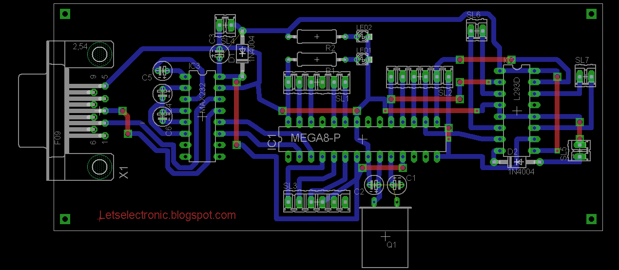
This is the advanced project thats i m going to do. In fact it include an ATMEGA MCU, a connectors for all his digital pins, and a max232/rs232 interface, a motor control based in l293D so we could just said thats we are making a developpement board for our MCU.
and like always here a long video demonstrate how i did that.
Good morning dears Followers, Today i came with a new idea not far than my last article. I m going to control the same robot but using a different way to command.
In my last article i showed how to control a Robot, Robotic Arm, Electronic system using C# and today i will demonstrate the same idea using one other software more professional in those kind of project which is in fact Labview.
Main Work
Like i mentionned in my last article, you have the choice to choose any MCU to make this project since the moment when this one contains UART.
My choice was selected in ATMEGA328, because i have a big part of the program ready from my last article. But even if you want to do this project using PIC or Arduino or STM32. The global fonctionnement is the same.
Let's take a look in our MCU.
This picture show that PIN 2 is the RX PIN and PIN 3 is the TX PIN and those two pin play the external interface given by the UART Module included in ATMEGA328.
So the Global idea of this project is : there is a graphic interface done in Labview who could communicate instantly and directly through serial port with an electronic circuit contains ATMEGA328.
This one every moment he receive a data through his UART module he will convert it to an ordre and give it to L293D Circuits.
L293D Circuits will amplify those ordres and give them to the robot motor.
The electronic circuit resume the idea.
The program that you have to put it in the MCU is:
void loop() { blinker(); Serial.begin(9600); if (Serial.available() > 0) { char a = Serial.read(); if ( a == '4'){robot_left(); } if ( a == '1'){robot_up();} if ( a == '3'){robot_right();} if ( a == '2'){robot_down();} if ( a == '0'){robot_stop();} }}
Now Let's speak about the graphic interface done in Labview.
Before all, For those who dont Know Labview take a look here:
In the official site ni.com they defined Labview like a highly productive development environment for creating custom applications that interact with real-world data or signals in fields such as science and engineering.
LabVIEW itself is a software development environment that contains numerous components, several of which are required for any type of test, measurement, or control application.
One of the best part of labview is the programming way which is totaly graphic, all what the programmer have to do is to collect the block and make tham work together and here an exemple.
In our interface we HAVE to use VISA, so what is VISA ?
In the same officialy site they defined VISA like The Virtual Instrument Software Architecture (VISA) a standard for configuring, programming, and troubleshooting instrumentation systems comprising GPIB, VXI, PXI, Serial, Ethernet, and/or USB interfaces. VISA provides the programming interface between the hardware and development environments such as LabVIEW, LabWindows/CVI, and Measurement Studio for Microsoft Visual Studio. NI-VISA is the National Instruments implementation of the VISA I/O standard. NI-VISA includes software libraries, interactive utilities such as NI I/O Trace and the VISA Interactive Control, and configuration programs through Measurement & Automation Explorer for all your development needs. NI-VISA is standard across the National Instruments product line. With NI-VISA, you can feel confident that your software development will not become obsolete as your instrumentation interface hardware needs evolve into the future.
One of the big part given by VISA is serial configuration.
Like i just said before the main idea of our project is based in serial communication.
So if you want to get it work you have just to be sure that's VISA driver is installed in your computer.
To make your own Graphic interface in Labview you have two panel to build, the design one and the programming one. and here is both of them.
Which make the global work inside Labview look like:
Using A virtuel Serial Port Driver you could test your work between ISIS and Labview and here is a demstrative Video.


![{\begin{aligned}H(z)&=\left[\sum _{{k=0}}^{{RM-1}}z^{{-k}}\right]^{N}\\&=\left({\frac {1-z^{{-RM}}}{1-z^{{-1}}}}\right)^{N}\end{aligned}}](https://wikimedia.org/api/rest_v1/media/math/render/svg/70337a643a2deaa2e85659f623f13eb005062eaf)